Current — Global Subsea Fiber Network Operator

We own the fiber under the ocean your traffic already crosses.

6 cable systems, 17 landing points across four regions, and over 41,000 kilometers of route — sold as lit wavelengths, dark fiber IRUs, landing-station colocation, and build-to-suit private systems to hyperscale cloud providers, carriers, and global enterprises.

41,100+ km Total route length
6 Cable systems, in service & under construction
17 Landing points across 4 regions
38.5ms Round-trip latency, New York–London

The Network

One network, four regions, no single point of failure

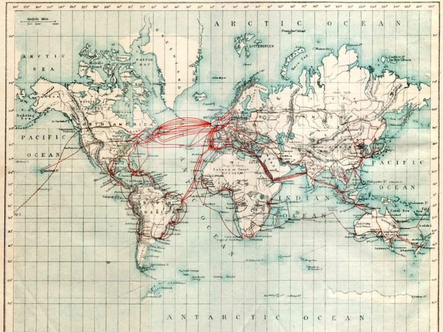
Every route below is a real, currently-operating or under-construction Current system — plotted by its actual landing-point coordinates, not a stylized abstraction.

Manasquan, NJ Bude, UK Hermosa Beach, CA Piti, Guam Chikura, Japan Tuas, Singapore Colombo, Sri Lanka Chennai, India Fortaleza, Brazil Praia, Cape Verde Sines, Portugal Marseille, France Alexandria, Egypt Fujairah, UAE Halifax, Canada Reykjavik, Iceland Galway, Ireland
Landing station (colocation facility) Cable landing point
4
Ocean regions served
98
Fiber pairs across the fleet
2,192 Tbps
Combined design capacity
15
Countries with a Current landing point

How A Subsea Cable System Actually Gets Built

From route survey to lit service

Every Current system follows the same six-stage build process — real marine engineering, not a metaphor for "advanced technology."

01

Marine route survey

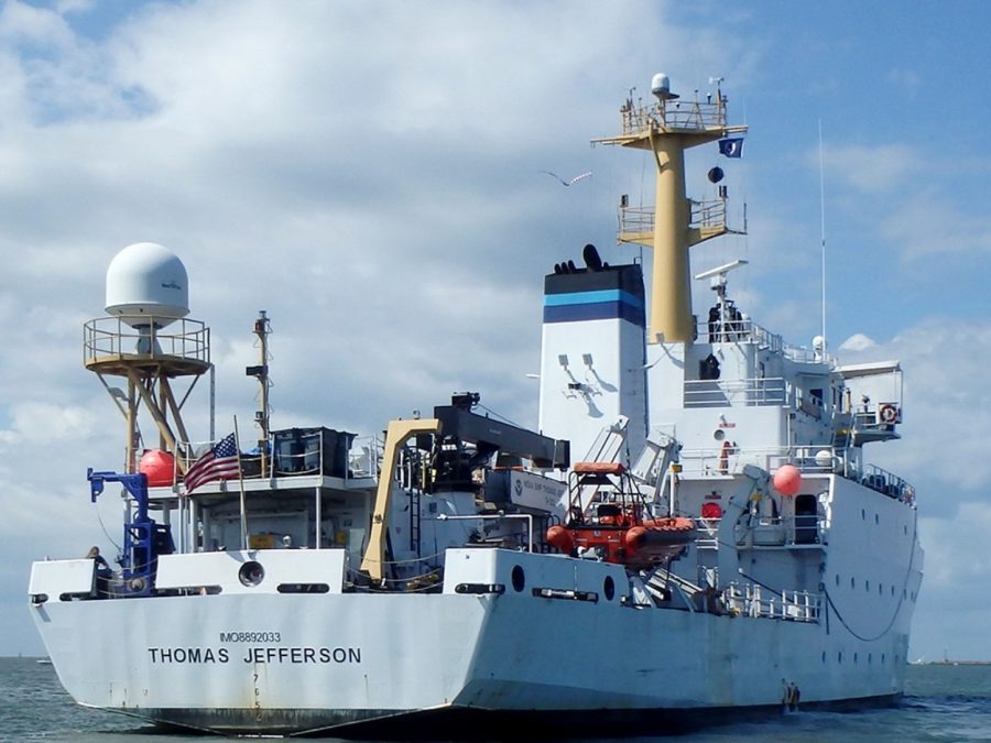
A dedicated survey vessel runs multibeam bathymetry, sub-bottom profiling, and seabed sampling along the full candidate corridor — confirming the seabed actually supports the planned burial depth and cable type before a single meter of cable is ordered. Any hazard the survey finds usually means adjusting the route.

02

Cable manufacture

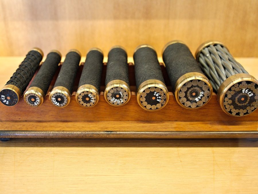
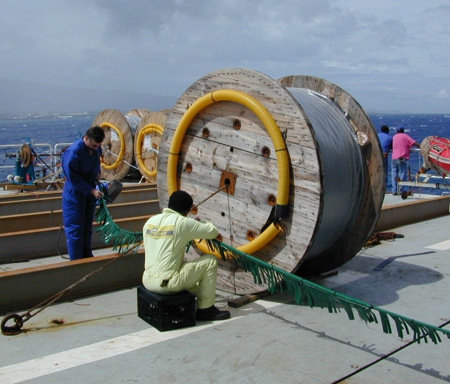
Cable is manufactured to the survey's exact route length and armoring specification — lightweight single-armor for stable deep-water sections, progressively heavier double- and rock-armored construction for shallow water and rocky seabed where mechanical protection matters most.

03

Cable-lay vessel deployment

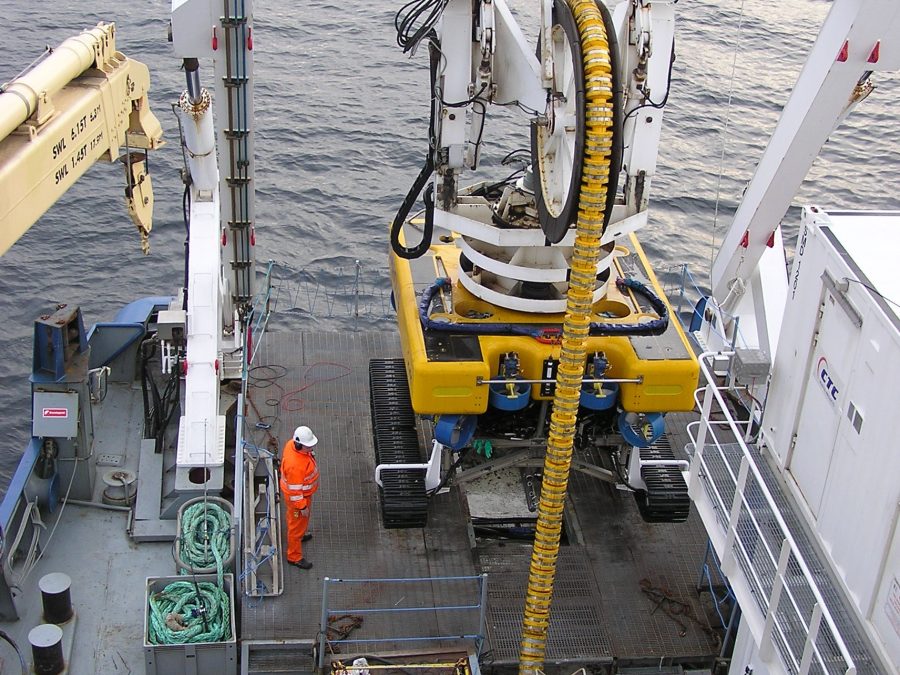
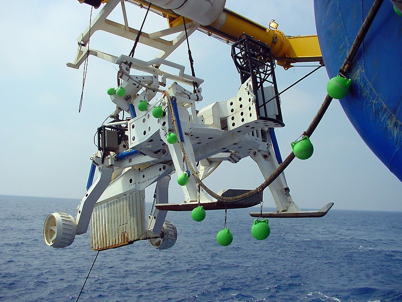
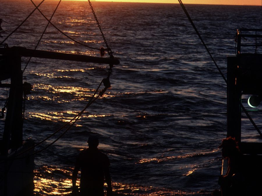
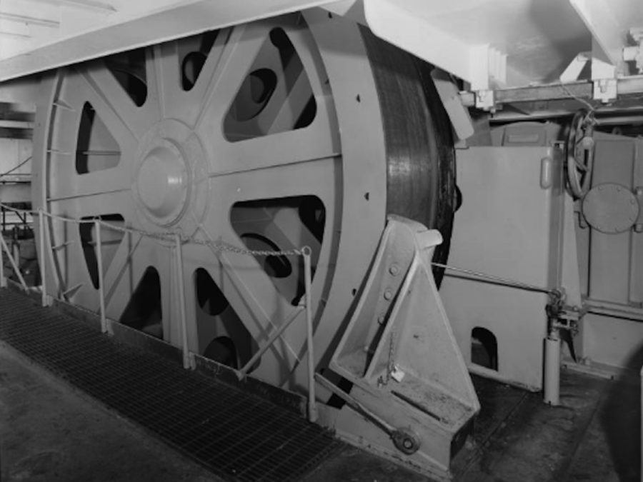
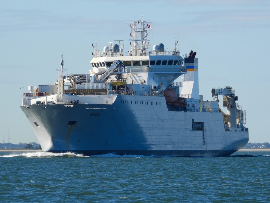
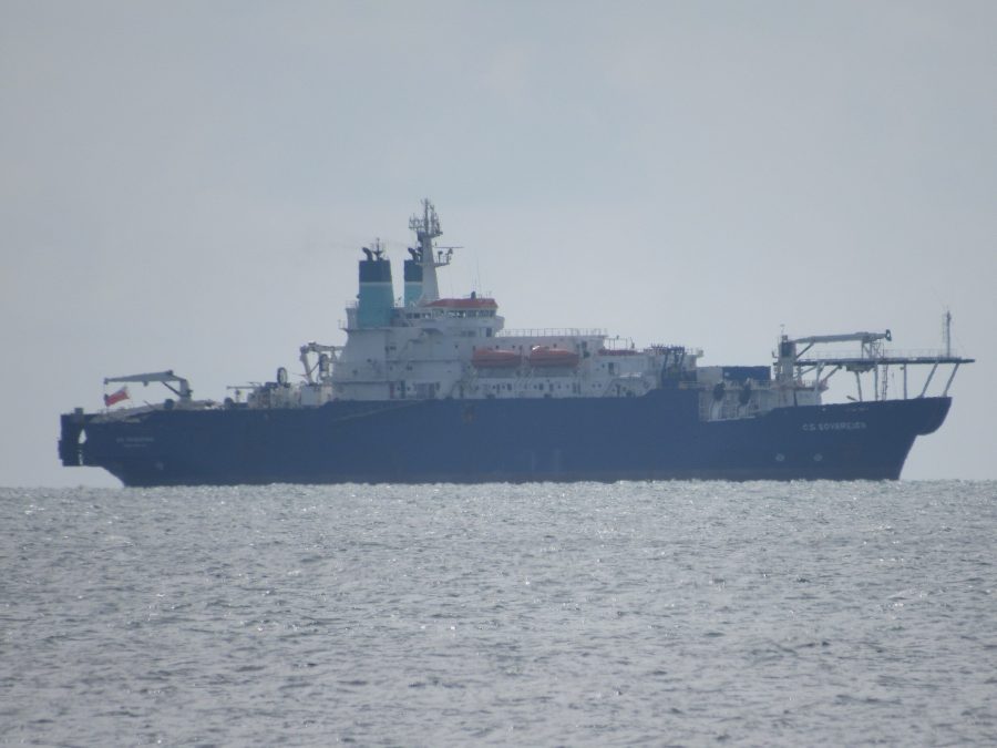
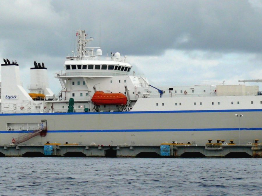
A purpose-built cable-lay ship pays cable out over the stern at a controlled rate matched to vessel speed and water depth, using dynamic positioning to hold route accuracy within meters — a slow, continuous operation that can run for weeks on a long-haul system.

04

Burial in shallow water, armor in deep water

Across the continental shelf — where anchor strikes and trawl gear cause most cable faults — cable is buried to a minimum 1.5-meter trench depth using a plough or jetting sled. Past the shelf, in the abyssal plain, double-armored construction is the primary protection instead.

05

Repeaters every 60–80 kilometers

Fiber attenuates roughly 0.18–0.20 dB per kilometer, so submerged optical amplifier housings are spliced into the cable at regular intervals to boost the signal before it degrades too far to recover — powered in series from shore, all the way to the far end.

06

Landing station & terrestrial backhaul

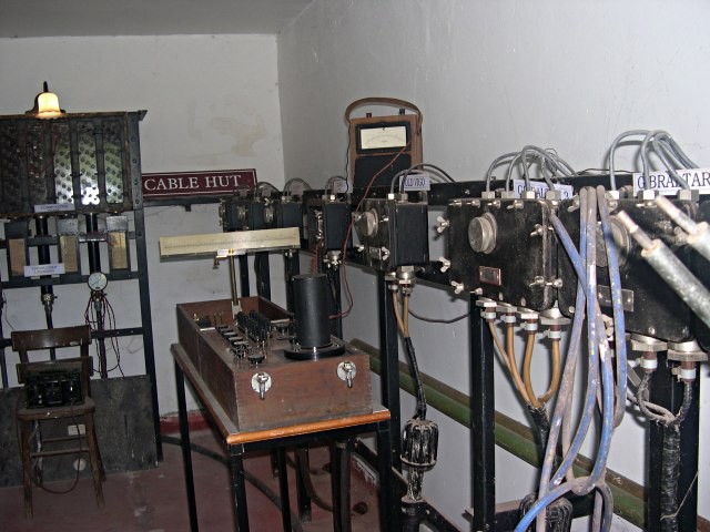
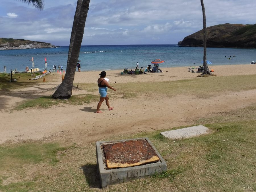
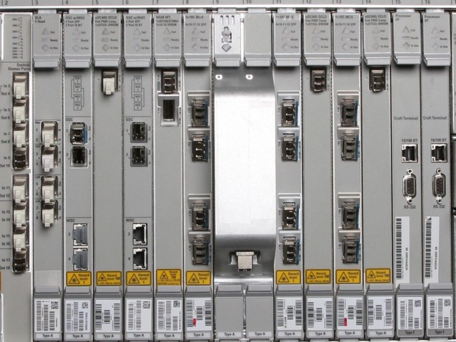
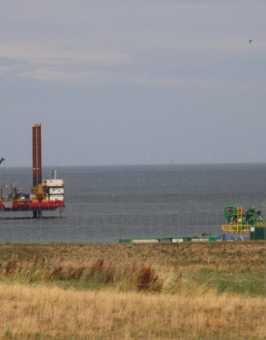
The cable comes ashore through a beach manhole into a landing station housing the line terminating equipment, then connects onward via terrestrial fiber into the nearest major interconnection hub — the point where the system becomes sellable capacity.

What We Sell

Four products, one underlying network

Most engagements start as a capacity conversation and evolve as requirements firm up — our team works route, latency, and diversity requirements alongside commercial structure from the first call.

Managed Service

Lit Capacity

Fully managed wavelength services from 10G to 800G per wavelength, delivered as a standard optical or Ethernet handoff. We handle provisioning, monitoring, and restoration.

  • 10G–800G per-wavelength options
  • Fastest path to service
  • SLA-backed restoration commitments

Long-Term Ownership

Dark Fiber / IRU

A 15–25 year indefeasible right of use over one or more dedicated fiber pairs on a named system — full control over your own capacity growth curve, lit with your own equipment on your own schedule.

  • 15–25 year IRU terms
  • Dedicated, exclusive fiber pairs
  • The default choice for hyperscale customers

Facility Access

Landing Station Colocation

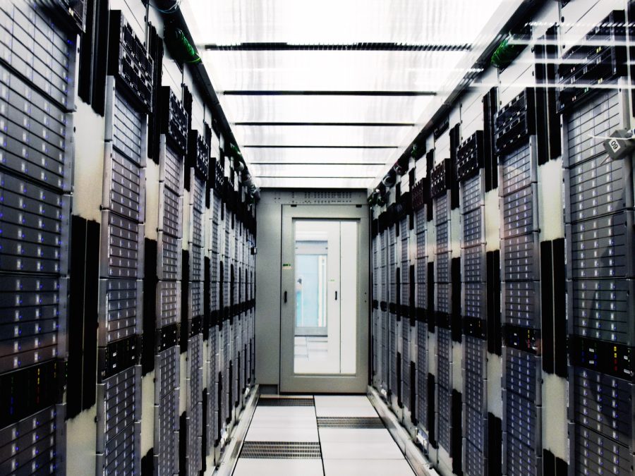
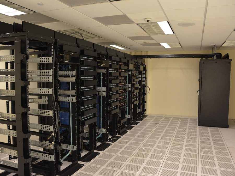
Rack space and power at any of our cable landing stations — place routing, switching, or compute equipment physically adjacent to the cable head instead of backhauling to an inland facility.

  • Single-rack up to dedicated private suites
  • High-density power options
  • Carrier-neutral cross-connect

Build-to-Suit

Private Cable Systems

A dedicated subsea system engineered, built, and optionally operated exclusively for one customer — full lifecycle management from route survey through ongoing maintenance.

  • Sole-customer route and capacity design
  • Full or controlling ownership available
  • Typical fit for sustained hyperscale demand

Cable Systems

Six named systems, four regions
View full network
Meridian-1 route overview
Manasquan, New Jersey, USA – Bude, Cornwall, UK

Meridian-1

Length
6,600 km
Fiber pairs
16 fiber pairs
Capacity
480 Tbps design capacity
Ready for service
2023
View system specs →
Tradewind Express route overview
Hermosa Beach, California, USA – Chikura, Chiba, Japan (branch to Piti, Guam)

Tradewind Express

Length
9,100 km
Fiber pairs
12 fiber pairs
Capacity
360 Tbps design capacity
Ready for service
2022
View system specs →
Amberline route overview
Tuas, Singapore – Colombo, Sri Lanka – Chennai, India

Amberline

Length
4,200 km
Fiber pairs
20 fiber pairs
Capacity
600 Tbps design capacity
Ready for service
2025
View system specs →
Solano Link route overview
Fortaleza, Brazil – Praia, Cape Verde – Sines, Portugal

Solano Link

Length
7,800 km
Fiber pairs
12 fiber pairs
Capacity
320 Tbps design capacity
Ready for service
2024
View system specs →
Kestrel Route route overview
Marseille, France – Alexandria, Egypt (terrestrial crossing) – Fujairah, UAE

Kestrel Route

Length
8,300 km submarine + 300 km terrestrial crossing
Fiber pairs
10 fiber pairs
Capacity
240 Tbps design capacity
Ready for service
2026
View system specs →
Boreal Span route overview
Halifax, Canada – Reykjavik, Iceland – Galway, Ireland

Boreal Span

Length
5,100 km
Fiber pairs
8 fiber pairs
Capacity
192 Tbps design capacity
Ready for service
2027
View system specs →

Landing Stations & Points of Presence

Facilities, not just cable heads

View all stations
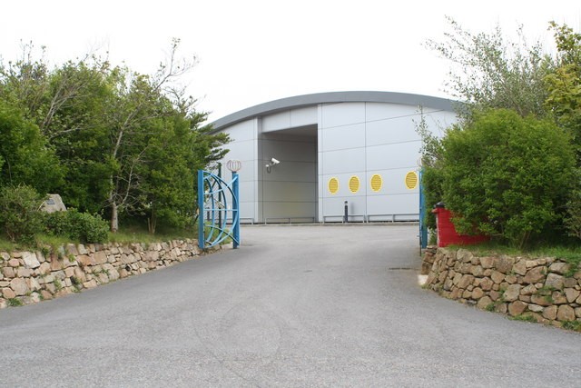
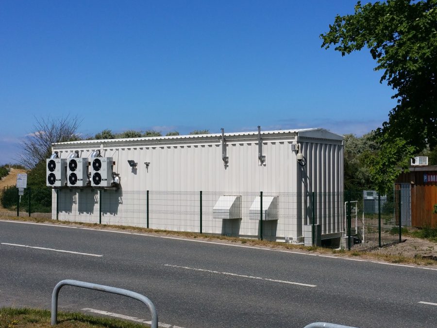
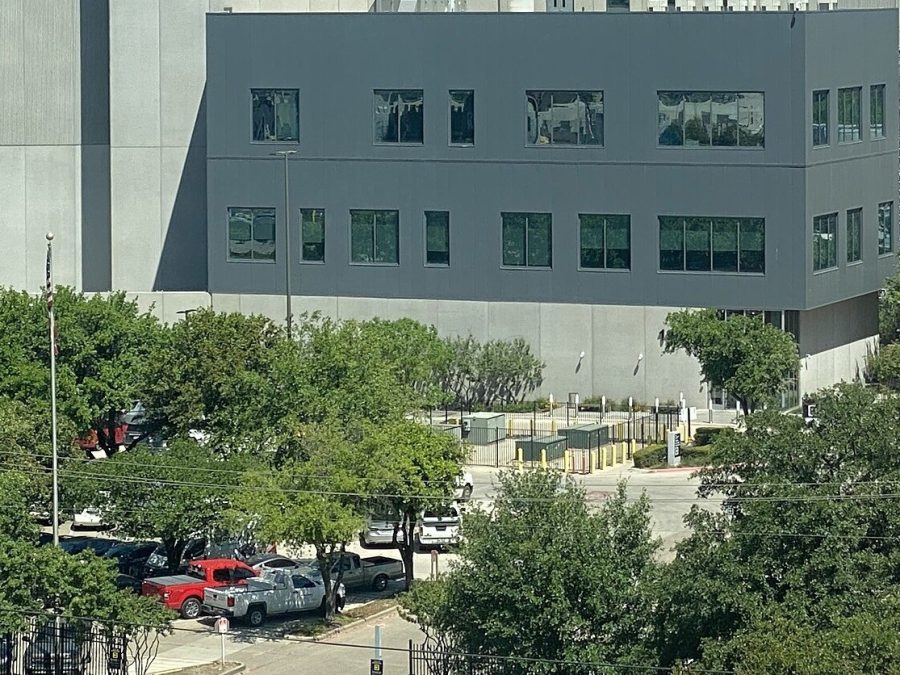
Bude Landing Station facility exterior

Bude Landing Station

Bude, Cornwall, United Kingdom
800 racks 12 MW critical power

Meridian-1's UK landing point on the Cornish coast — 800-rack colocation campus with 12 MW of critical power.

View facility →
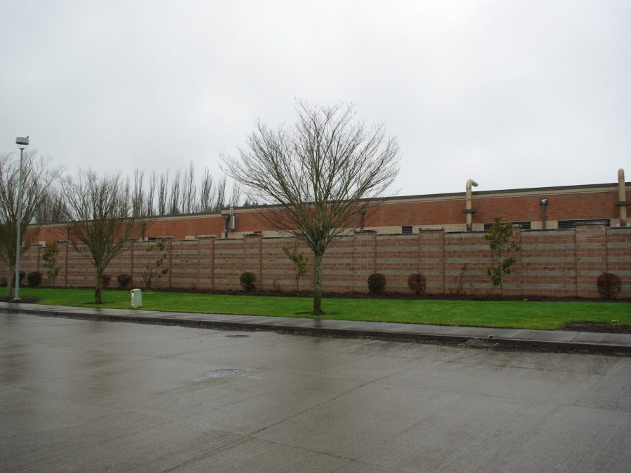
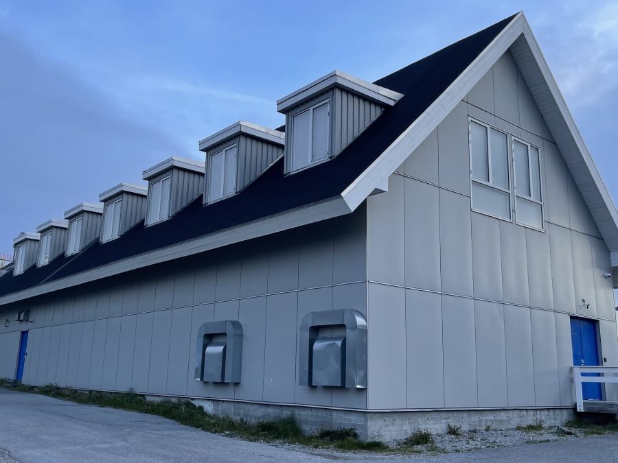
Manasquan Cable Landing Station facility exterior

Manasquan Cable Landing Station

Manasquan, New Jersey, USA
600 racks 9 MW critical power

Meridian-1's US landing point on the New Jersey shore — 600 racks and 9 MW, with direct terrestrial backhaul into…

View facility →
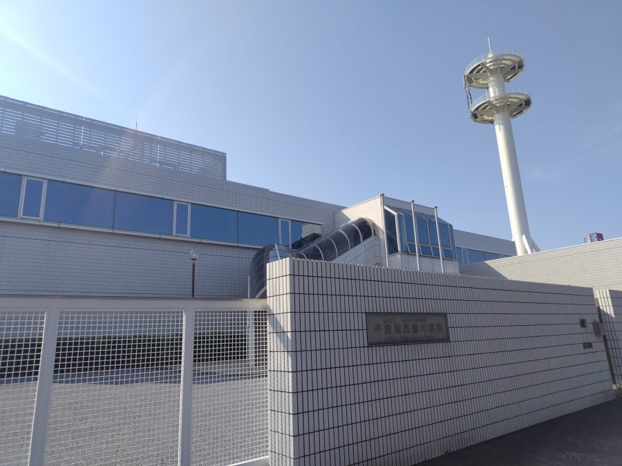
Chikura Landing Station facility exterior

Chikura Landing Station

Chikura, Chiba Prefecture, Japan
500 racks 8 MW critical power

Tradewind Express's Japan landing point in Chiba Prefecture — 500 racks and 8 MW, with onward backhaul into Tokyo.

View facility →
Tuas Landing Station facility exterior

Tuas Landing Station

Tuas, Singapore
1,200 racks 18 MW critical power

Current's flagship Asia-Pacific hub — 1,200 racks and 18 MW, the shared landing point for Amberline and the Tradewind Express…

View facility →
Sines Landing Station facility exterior

Sines Landing Station

Sines, Portugal
700 racks 10 MW critical power

Solano Link's European landing point on Portugal's Atlantic coast — 700 racks and 10 MW, plus an on-campus subsea data…

View facility →

Scroll for more →

Why Current

What buyers actually diligence before signing

01

Genuine physical route diversity

Diverse routes across different landing stations, marine corridors, and terrestrial backhaul paths — not two cables that happen to land at the same facility.

02

A real permitting track record

Every system we've built has closed marine and terrestrial permitting across every coastal state on its route, including a multi-country terrestrial crossing on Kestrel Route.

03

Our own marine maintenance fleet

Dedicated cable-lay and repair vessels on standby across our operating zones — repairs don't wait on a third-party contractor's availability.

04

SLA-backed restoration commitments

Published mean-time-to-repair targets by zone, with restoration priority contractually defined — not a best-effort promise.

05

Engineering-led sales process

Route and latency questions get answered by the engineers who'd actually build your system, from the first call — not routed to a separate technical team after signature.

06

Consortium and private-system flexibility

Wholly-owned systems, multi-party consortiums, and single-customer private builds — whichever ownership structure actually fits your capital and control requirements.

Client Outcomes

What this looks like in practice

Hyperscale Cloud Provider

2
physically diverse cable systems, 3 lit fiber pairs total

“A top-five hyperscale cloud provider needed guaranteed physically diverse capacity into a new Southeast Asian availability-zone region ahead of a public launch date, with zero tolerance for a single shared failure point across the two routes.”

Delivered across Amberline and a third-party diverse route, ready for service 14 months ahead of the customer's public region launch.

Tier-1 International Carrier

100%
route and landing-station diversity from the existing primary path

“A Tier-1 international carrier's primary transatlantic capacity ran entirely through one cable landing corridor — a genuine single point of failure the carrier's own risk audit flagged as unacceptable for their SLA commitments.”

A long-term dark fiber IRU on Boreal Span, chosen specifically for zero corridor or facility overlap with the carrier's existing route.

Proprietary Trading Firm

38.5ms
measured round-trip latency, within 0.3ms of the physical fiber-length minimum

“A proprietary trading firm needed the lowest achievable, deterministic round-trip latency between two specific financial data centers — measured in fractions of a millisecond, not a general bandwidth requirement.”

A dedicated wavelength on Meridian-1's most direct routing, with terminal equipment placement optimized specifically to minimize processing delay.

A marine environmental survey being conducted ahead of route planning A laid cable's minimal physical footprint on the seafloor

Environmental Practice

A genuinely small physical footprint, verified before we lay a meter of cable

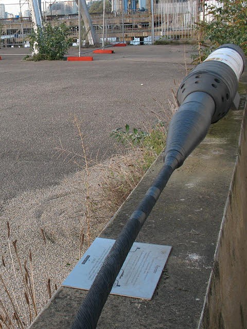
A subsea cable is roughly the diameter of a garden hose once armored, laid on or just beneath the seafloor along a corridor typically a few meters wide — one of the smallest physical footprints of any piece of intercontinental infrastructure, and unlike a pipeline or a power interconnector, it carries no risk of a substance leak.

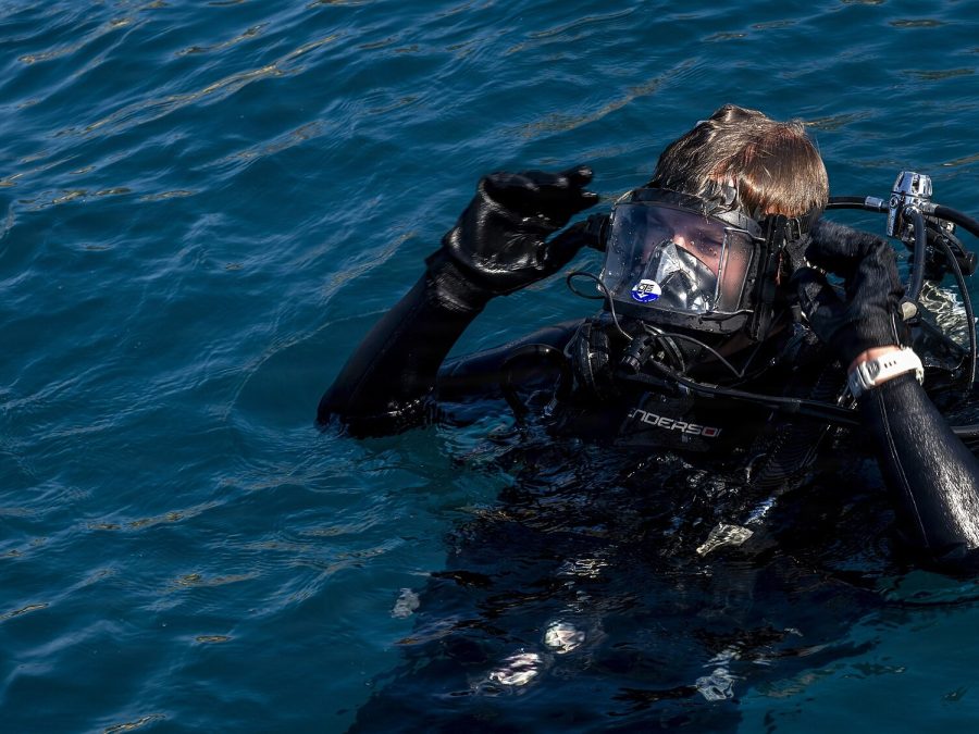
Every route goes through a formal marine environmental impact assessment before permitting, specifically routing around known sensitive habitats — coral reefs, seagrass beds, and spawning grounds identified during survey are treated as hard route constraints, not areas to minimize crossing through.

  • Typical armored cable diameter 17–50mm
  • Typical seabed corridor disturbed during lay <5m wide
  • Systems built with sensitive-habitat routing constraints 100%
  • Substance leak risk None — no fluids carried

The Fleet

The vessels that build and maintain the network

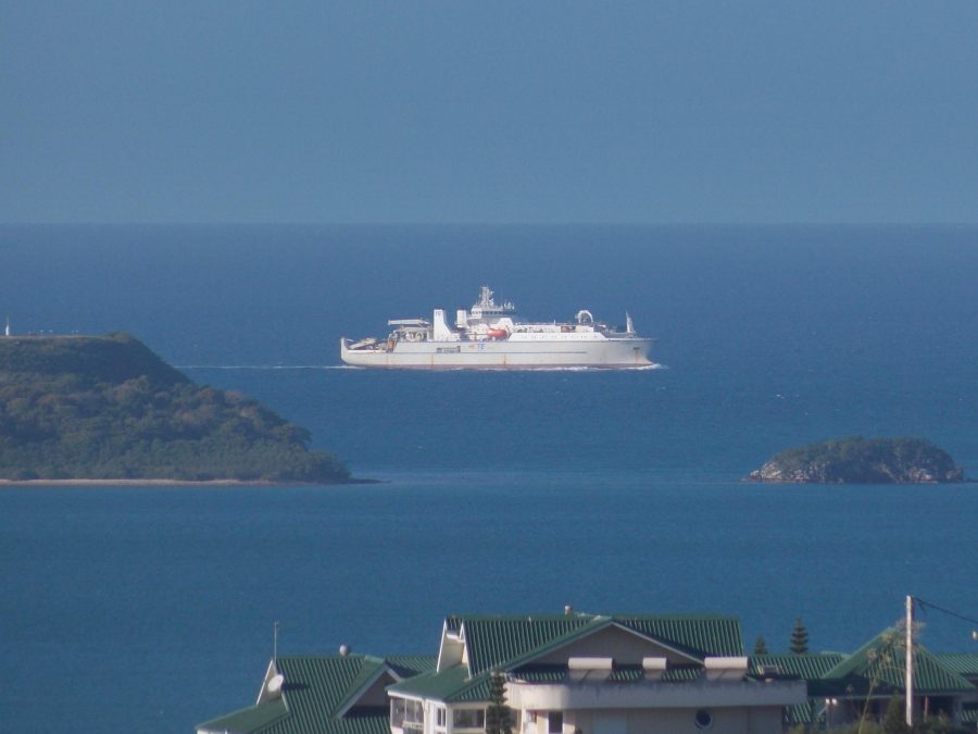
CS Current Pioneer — Cable-Lay Vessel — Atlantic & Mediterranean

CS Current Pioneer

Cable-Lay Vessel — Atlantic & Mediterranean

138m LOA, 6,000-tonne cable capacity, DP2 dynamic positioning, dual linear cable engines. Lead lay vessel on Meridian-1, Solano Link, and Kestrel Route.

CS Meridian Guardian — Maintenance & Repair Vessel — Atlantic Zone

CS Meridian Guardian

Maintenance & Repair Vessel — Atlantic Zone

115m LOA, grapnel and ROV repair spread, on 24-hour standby across our Atlantic maintenance zone under a dedicated repair contract.

RV Current Surveyor — Route Survey Vessel

RV Current Surveyor

Route Survey Vessel

78m LOA, multibeam bathymetry, sub-bottom profiler, and ROV survey package. Runs every pre-lay route and hazard survey across our active build pipeline.

CS Tradewind Carrier — Cable-Lay Vessel — Pacific

CS Tradewind Carrier

Cable-Lay Vessel — Pacific

154m LOA, 8,500-tonne cable capacity, twin laying towers, integrated burial plough. Lead lay vessel on Tradewind Express and Amberline.

From Insights

Technical notes on capacity, latency, and marine engineering

Read Insights

Request Capacity

Tell us your route and your ready-for-service date.

Every RFP is routed directly to a member of our capacity sales team, with engineering included from the first call for route, latency, or diversity-sensitive requirements.

Current Networks, Inc. 1 Landing Point Plaza, Suite 1400 New York, NY 10004